
Small scale hydronic cooling
February 15, 2019 | By John Siegenthaler
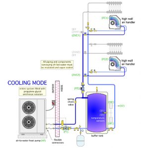
Figure 1 Zoned distribution system
Hydronic heating has long been known for providing superior cold weather comfort. Even so, the question that often comes from potential clients who are already convinced about of the benefits of hydronic heating, is: “What do I do about cooling?”
In the days when nearly all hydronic heating systems were supplied by boilers, the answer to this question was to install a separate cooling system. It might be a standard ducted system where an outdoor condenser unit supplied a single air handler in the building. The cooled and dehumidified air was then routed through a ducted forced air system.
The potential customer’s argument was typically: Why should I pay to install a hydronic heating system and then pay several thousand dollars more for a fully ducted cooling system, when the ducted system could also be used for distributing heated air? In some cases the allure of superior comfort, especially that provided by a hydronic radiant panel heating system, was sufficient justification for this “two separate systems” approach. However, when the construction budget was the controlling factor, the “ducts can do both” option typically doomed the hydronic heating system in favour of a furnace topped with an A-coil for cooling.
Today, there are many indicators that point to heat pumps gaining a greater share of the hydronic heat source market. There is also a significant overlap between heat pumps and hydronic technology. Geothermal water-to-water heat pumps, as well as air-to-water heat pumps, stand ready, willing and able to supply warm water for low temperature radiant panel heat systems in all areas of North America.
In many areas of North America, geothermal heat pumps currently enjoy generous subsidies that cover their higher installation cost. Air-to-water heat pumps, although currently not subsidized in most markets, can still hold their own on the basis of cost competitive performance, even in cold climates.
The icing on the cake: In addition to their ability to serve as high performance hydronic heat sources, nearly all currently available geothermal water-to-water heat pumps, and air-to-water heat pumps, come with refrigerant reversing valves and associated control logic that allows them to function as chillers. That’s a game changer when the question “but what do I do about cooling” comes up with prospective clients.
A typical hydronic heat pump (water-to-water or air-to-water) can produce chilled fluids with temperature down to about 40F. Those temperatures are very sufficient for both sensible and latent cooling. All that is needed is a way to interface this chilled fluid with interior space in a way that produces comfortable air temperatures and humidity levels. That interface should also take advantage of the benefits offered by hydronic delivery system, such as zoning, high distribution efficiency, and minimal invasiveness.
There are several possibilities. Let’s take a look.
One approach is to set up a zoned distribution system serving multiple fan-coil units, such as depicted in Figure 1.
This system, shown in cooling mode operation, uses an air-to-water heat pump to supply two zones of radiant panel heating, or two zones of cooling.
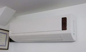
Figure 2 High wall vent
To ensure freeze protection of the outdoor heat pump, the entire system operates with a 30 per cent solution of inhibited propylene glycol antifreeze. Some manufacturers also offer “split system” air-to-water heat pumps that only contain refrigerant in the outdoor unit. This eliminates any concern for freezing in the outdoor unit. All piping carrying chilled fluid must be insulated and vapour sealed to prevent condensation. Although this is a simple concept, it remains a challenge in practice, especially for installers not used to insulating piping in hydronic heating systems.
When piping insulation is not properly done condensation on piping, valves, and circulators is sure to occur. That condensate can drip onto drywall surfaces and produce stains in short order. If you are not willing and able to do the insulation system right, do not get involved with any chilled fluid cooling system.
In Figure 1, chilled water is prevented from migrating into the radiant panel zones by a combination of a closed zone valve on the supply pipe and a check valve on the return side piping.
A variable speed circulator provides flow to the radiant panel manifold stations, or the air handlers, depending on operating mode. Zone valves determine which manifold or air handler receives flow. The circulator automatically adjusts speed as zone valves open or close.
The buffer tank prevents the heat pump from short cycling when only one zone is operating.
TERMINAL VARIATIONS
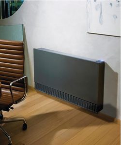
Figure 3 Console fan-coil
The fan-coils depicted in Figure 1 are called “high wall” units. Figure 2 shows an example of such a unit installed about six inches below ceiling level.
High wall hydronic fan-coils are virtually identical to the air handlers used on many mini-split heat pump systems. The only significant difference is that the hydronic air handler has a water coil, rather than a direct expansion (refrigerant) coil.
Hydronic high wall air handlers are currently available from several North American suppliers. They are typically turned or or off using a remote, and sport features such as vertically oscillating air diffusers, variable speed blowers, and different control modes for cooling, heating, and dehumidification. These air handlers come with condensate drainage tubes that can either be routed through an exterior wall, or connected to 3⁄4 inch plastic drainage piping routed through partitions.
It is also possible to use “console” fan-coil units such as the unit shown in Figure 1.
Console fan coils can be surface mounted or recessed into wall cavities. The later arguably looks better, but requires coordination with wall framing to ensure the recessed cavity is located and sized correctly.
Yet another possibility is one or more ducted air handlers. These are widely available with both vertical or horizontal cabinet configurations. An example of the latter is shown in Figure 4.
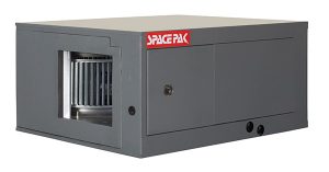
Figure 4 Ducted horizontal air handler
Some ducted air handlers are designed to connect to standard ducting systems. Others are designed as “high velocity” units with blowers that generate high static pressure. the latter are typically configured with a single trunk duct that supplies several flexible two-inch diameter branch ducts.
These small branch ducts can be snaked through partitions or along framing cavities. They terminate in a small orifice mounted on a ceiling or wall. Typically there needs to be six or seven branch ducts per ton (12,000 Btuh) of cooling capacity. The branch ducts are typically limited to runs of 25 feet from where they connect to the trunk duct.
Figure 5 shows an example of a horizontal air handler mounted within a conditioned attic space. The small two-inch flex ducts supplied from the single trunk are seen fastened to the insulated roof surface. If you look closely you will also see a secondary drain pan under the air handler. It is there in case the drain pan within the air handler develops a leak, or the piping from that drip pan somehow gets plugged. A secondary drain pan is cheap insurance against the possibility of a condensate leak that could damage expensive interior surfaces under the air handler.
PAY ATTENTION
Whenever a fan-coil or air handler is used for chilled fluid cooling it is important to understand, respect, and implement several details:
- Always be sure that the air handler or fan coil is equipped with a condensate drip pan and drain tube.
- Be sure to plan for how electrical power, an insulated supply and return pipe, and a condensate drain tube will be routed to each air handler or fan coil.
- When a recessed fan coil is used be sure to provide framers or other construction contractors with information on the size and exact location of the wall cavity.
- Be sure to pitch the condensate drainage tube to allow gravity drainage.
- If the condensate drain is connected to the building’s DWV plumbing system be sure to install traps that prevent sewer gas from reaching the air handler or fan coil. Follow applicable code requirements for the trap details.
- Place air handlers or fan coils so that air discharge is not directly aimed at areas where occupants are seated. Drafts create discomfort.
- Always get a wiring diagram for the specific air handler or fan coil being used so that it functionality can be coordinated with other control functions such as turning on the distribution circulator and heat pump.
COOL SURFACES
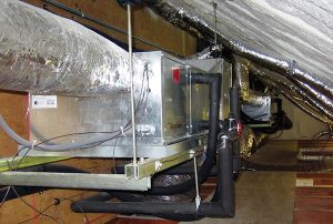
Figure 5 Air handler in conditioned space
Another option is radiant panel cooling. This technology enjoys a more developed market in Europe, but is currently in its infancy within North America. It involves circulating a chilled fluid (water or an antifreeze solution) thorough radiant panel tubing circuits embedded in ceilings, walls, or floors. Of these, radiant ceilings are ideal for cooling.
A key concept is to regulate the chilled fluid temperature to the radiant panel so that it remains just above the dewpoint temperature of the space being cooled. This is critically important in avoiding condensation on the panel.
The May 2014 HPAC article “I Need This Controller” covers the details and possible piping/control designs for radiant cooling. Check it out in the HPAC archives for more information. <>
John Siegenthaler, P.E., is a mechanical engineering graduate of Rensselaer Polytechnic Institute and a licensed professional engineer. He has over 34 years experience in designing modern hydronic heating systems. Siegenthaler’s latest book is Heating with Renewable Energy (see www.hydronicpros.com for more information).

